
SMT SMART TWEEZERS ST5-AS
Professional Highest-Precision R-L-C Meter
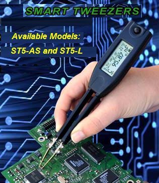
SMD Pre-Calibrated Components Identifier in a Set of Tweezers
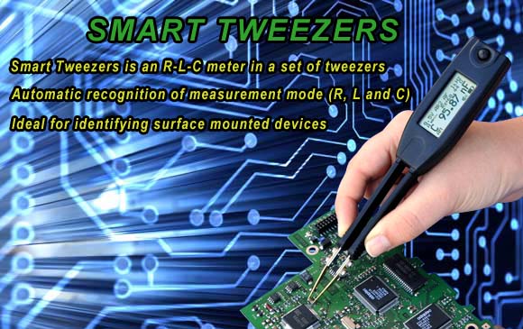

Smart Tweezers is an R-L-C meter in a set of tweezers. Smart Tweezers features a unique patented mechanical and electronic design that incorporates a built-in direct precision SMD probe designed for component evaluation on the production line, component impedance testing and sorting of SMD components. Smart Tweezers dramatically cuts the time necessary to troubleshoot and debug a complex PCB making process of locating of a faulty component a breeze.
The integrated SMD probe and graphic display, combined with automatic recognition of measurement modes (R, C, and L) and the range of measurement, allow the operator to focus on the component under test. As a result, testing, sorting and evaluation of components become more efficient and cost effective.
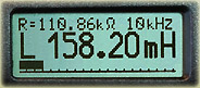
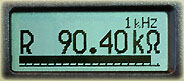
The primary display shows the present reading. The secondary display (on top) shows the present reading of additional parameters or measurement conditions when the primary display shows some other feature (L, C). When multiple features present, the secondary display shows one of the values. The Bar Graph provides an analog indication of the measured input.
 |
 |
Smart Tweezers features a JOG DIAL button to choose modifiers for a selected function or change the setting. Rotate the JOG DIAL button to choose from a list of functions, then press to activate this function and see it appear on the display.
| AC test mode Test frequency | 1 kHz, 10 kHz, 120Hz, 100 Hz |
| Test frequency accuracy | 50 PPM (0.005%) |
| Test signal level | 0.25/0.5/1.0 +/- 5% VRMS Sine wave |
| Source impedance | 62.5Ω/1kΩ/16kΩ +/- 1% |
| Parameter | Measurement Range | Basic Measurement Accuracy* |
|---|---|---|
| Resistance* | 5 Ω to 999 kΩ 0.1 to 9.9 MΩ |
< 0.2% < 1.0% |
| Capacitance* | 10 pF to 100 μF 0.5 pF to 999 μF |
< 0.5% < 1.0% |
| Q | 0.001 to 100 | |
| Inductance* | 10 μH to 99 mH 0.5 μH to 999 mH |
< 0.5% < 1.0% |
| D | 0.001 to 10 |
* at optimum test frequencies, ranges, without calibration offset. ** required DC voltage offset calibration
| Auto mode Read-out | Dominant parameter |
| Equivalent circuit diagram | Serial/Parallel for C/R Serial for L/R |
| Manual Mode Read-out | Dominant or secondary parameter |
| Equivalent circuit diagram | Parallel or serial |
| Measurement update rate | up to 4 measurements per second |
| Battery Type | 3.7V LiPO rechargeable 150mAH |
| Typical charge time | 2.5 hours, current <100mA |
| Calibration | Recommended interval 1 year. NIST traceable calibration |
| Size | 14.0 x 2.5 x 3.0 cm (3.94 x 0.9 x 1.5 in) |
| Weight | 53 grams (0.11 lb) |
| Operating temperature | 0°C to 50°C |
| Storage temperature | -40°C to 70°C |
| Relative Humidity | 0 % to 90 % (0 °C to 35 °C) |
| Altitude Operating | 0 – 2000 meters |
| EMC | According to CE regulation 89/336, Emission according FCC15 Class B |
| Parameter | Measurement Range | Basic Measurement Accuracy* |
|---|---|---|
| Resistance | 1Ω to 999 kΩ | < 0.2% |
| 0.1 to 9.9 MΩ | < 0.5% | |
| Capacitance | 10 pF to 100 μF | < 0.5% |
| 0.5 pF to 999 μF | < 1.0% | |
| Inductance | 10 μH to 99 mH | < 0.5% |
| 0.5 μH to 999 mH | < 1.0% |
* at optimum test frequency, ranges, without calibration offset
| Resistance | ≤ 25 mΩ |
| Capacitance | 0.65 pF |
| Inductance | 0.1 uH |
Offset value should be subtracted from measurement result for small value components (R < 10Ω, C < 100 pF, L < 10 μH).
| Parameter | Measurement Range | Test frequency |
|---|---|---|
| Resistance | < 9.9 MΩ | 1 kHz |
| Capacitance | < 9999 pF | 10 kHz |
| 10000 pF to 1 μF | 1 kHz | |
| > 1 uF | 100 Hz | |
| Inductance | 0.5 μH to 99 μH | 10 kHz |
| 100 μH 99 mH | 1 kHz | |
| > 100 mH | 100 Hz |
| Resistance R | 0.05 Ω to 9.9 MΩ |
| Capacitance C | 0.5 pF to 999 μF |
| Inductance L | 0.5 μH to 999 mH |
| Quality factor Q | 0.001 to 1000 * |
| Dissipation factor D | 0.001 to 1000 * |
| Impedance/Resistance Z or RAC | 10 mΩ |
| Capacitance C | 0.1 pF |
| Inductance L | 0.1 μH |
| Quality factor Q | 0.001 |
| Dissipation factor D | 0.001 |
* indication of the parameter not implemented in some versions
| www.smt-tool.com | www.intelligenttweezers.com |